Hydropower plant are amazing engineering constructions that take years to plan and construct. This page is an introduction to hydropower plans and dam design, so you easily can get an idea of how they work and what it takes to design and construct a hydropower plant.
Hydropower
Hydropower or the energy contained in flowing water has been known for many thousand years and has been used to perform various types of work. The Romans were familiar with the waterwheel but didn’t use systematically, and it was not until the fourteenth century that it became widespread. The power output of these early plants was typically limited to around 100 kW (Deudney, 1981).
The development of modern hydropower plants started in the 1820s when Benoit Fourneyron created a turbine with approximately 80 percent efficiency. This concept was further developed by S. Howd and U. A. Boyden and later by James B. Francis, who made a turbine in 1848 with 90 percent efficiency. It was named Francis after him.
The two other main types of turbines, the Pelton and the Kaplan, were developed respectively around the turn of the century and in the 1920s. Development of both efficiency and size of the plants has continued up through the century and today the best turbines have approximately 95 percent efficiency. The largest plant is the Three Gorges project in China, which has an installed capacity of 18.200 MW (Wikipedia three gorges dam).
The most widely used of the three is the Francis turbine because it is the turbine that can operate under the largest variation of head and discharge
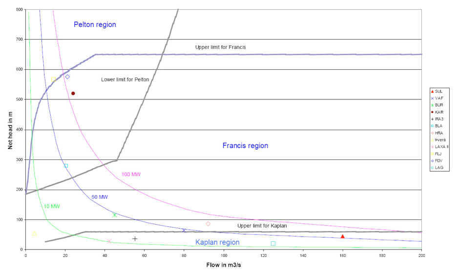
The Francis turbine can both be an impulse or reaction turbine depending on the size of the flow it is designed to accommodate. Low flow Francis turbines are impulse turbines whereas they are reaction for high flow. The main difference between the Kaplan (reaction) and the Francis is that the Kaplan has adjustable runner blades whereas they are fixed on the Francis. It makes the Kaplan more suitable for low head schemes with a high discharge as shown on Figure 2. The Pelton turbine is on the other hand an impulse turbine, which makes it best suited for the highest hydraulic heads.
All hydropower plants are different in some way, because the topography of the area they are located in determines the layout. Hydropower plants can be divided into three main groups according to function of the storage:
- Run of the river plants
- Storage regulated plants
- Pumped storage plants
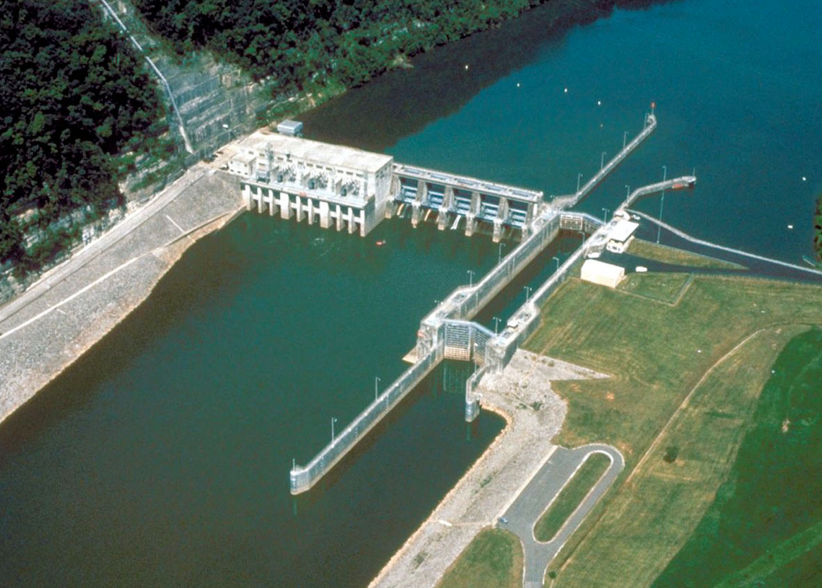
Run of the river plants
Run of the river plants feed directly off the river (Cordel Hul Lock). That makes them most suitable for rivers with a relatively constant discharge or in a market with good possibilities of substitution.
Storage regulated plants
Storage regulated plants (Itaipu) have the possibility to utilise the vast majority of the water even in rivers with large seasonal fluctuations. The size of the reservoir determines how well the plant can accommodate fluctuations including daily fluctuations in power demand.

Pumped storage plants
Pumped storage plants (Dinorwing pumped storage), on the other hand, don’t produce electricity overall, but are used to store cheap off-peak electricity that is utilized during peak hours. They store the cheap off peak electricity by using it to pump water from a low reservoir to a high reservoir, and during peak hour it is operated like a conversional hydropower plant.
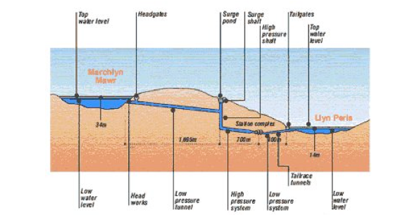
Dinorwing pumped storage shows the general concept of a storage regulated or pumped storage hydropower plant. The reservoir is formed by a dam that either creates a new or raises the water level in an existing lake. From the reservoir the water is conveyed to a surge facility by the headrace channel and/or tunnel. The surge facility is used to accommodate for rapid changes in the flow through the station by either supplying or dissipating energy. This is a very important function as it prevents water hammering from damaging the headrace tunnel in case of sudden shunt downs and air from entering the turbines in case rapid pick-ups. The water is lead from the surge facility to the turbines by the penstock and from there on to the erection bay.
Dam Design
Dams are designed in many different ways and no two dams are similar, since each is specially design for the site. They are designed to fit the topography of the site, the foundation conditions, the materials available and according to any site specific loads i.e. traffic, ice. Their location and crest elevation is the result of a general optimization of the hydro electric project they are a part of, and the final design of high dams is a complicated engineering achievement that involves civil engineering disciplines.
Dams can be divided into three main types, gravity dams, arc dams and earthfill/rockfill dams. A gravity dam is rigid element, typically made of concrete and the stability is secured by designing it in such a way that the shape and mass prevents it from overturning and/or sliding on the foundation.
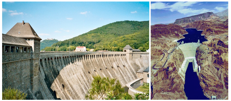
The second type is the arc dam. It is also a rigid concrete structure, but the stability is secured partly by the gravity of the dam itself and by the arc transferring the remaining stress into the foundation. Thus, the foundation needs to be very good in order to carry the stresses introduced by the arc
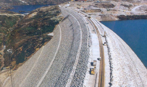
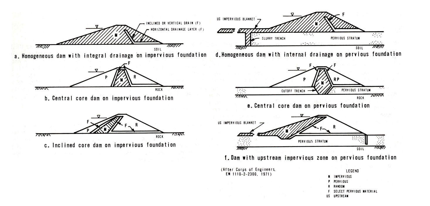
The third type is the earthfill/rockfill dam, which consists of crushed rock or/and various types of soils. It is a triangular structure with an impervious core or layer on the upstream side. The core typically consists of clay, concrete or asphalt, whereas an impervious upstream face often consists of asphalt or concrete. The stability of the slopes is governed by Equation 1, which states that the shear strength of a soil consists of two components, cohesion and friction.
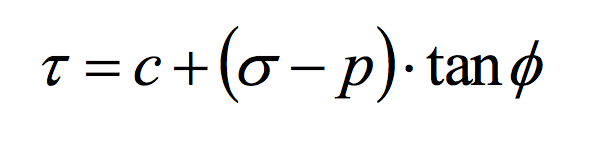
The cohesion and the angle of friction are material properties, whereas the pore pressure is governed by the type and location of the impervious element and the adjacent filter material. The normal stress on the other hand is governed by the height of the dam and the density of the fill. Thus the slope stability and width of the dam is a function of the location of the impervious element and the type of material used. The full strength of the soils are never used in dam design, since an operational factor of safety of 1,5 is the norm (Equation 2).

The materials used in dams are hauled as close to the site as possible since the transport of them from the quarries to the site represents a significant part of the total cost of building a dam. Hence, the cross section of a rock/earthfill dam varies depending on what materials that is available on site, and their properties.
Beside retaining the water, a dam has to resist external loads like traffic across it and ice pressure if the reservoir is covered with ice. If it is located in a seismic active zone, the earthquakes are often the governing parameters, hence they have to be considered carefully in the design of the dam. Further, it has to have sufficient freeboard[3] to ensure no overtopping by high waves or floods.
Dam failures
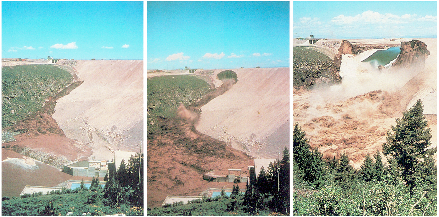
Though dam failures are very rare several have occurred and the most common reasons for failure are internal erosion, overtopping and liquefaction during earthquakes (Wilson et al, 1979). The most famous failure caused by internal erosion is the collapse of the 90 meter high Teton dam in 1976 during first filling. It failed due to a combination of several open joints in the right abutment rocks and the fact that the impervious fill was very erodible (Wilson et al, 1979).
The second reason, overtopping, is mainly caused by either insufficient spillways compared with flood sizes or by operational problems with the spillway i.e. the gates (Wilson et al, 1979). It can also be caused by wind generated waves specially in large reservoirs, thus it has to be considered in the calculation of the freeboard. The third reason is liquefaction, which is a phenomenon that can arise during earthquakes in saturated sand and silt, since they are cohesionless soils. The earthquake load densifies the soil which causes the pore pressure to increase and the effective stress to decrease if the soil is undrained which causes the soil to behave more like a liquid (see Equation 1) (Kramer, 1996). The near failure of the Lower San Fernando Dam in 1971 during a Richter 6,6 earthquake was caused by liquefaction in the hydraulic fill near the base of the foundation (Seed et al, 1975).

About Jakob Madsen
Jakob Madsen is a danish engineer turned entrepreneur. The introduction to dam design is part of his thesis from 2006 which is called: Optimal design of Hydropower Plants. You can read some of the other sections on qaits.com
Today, Jakob Madsen is the founder of Bookanaut and Vupea.com. Bookanaut is a platform for sport and health which he has founded together with Lasse Lundberg and Morning Train. Forsikring.io is a guide to insurance which he has founded together with Nanna Gorm.
You are always more than welcome to contact him at:
Boman Consulting
Kløvermarksvej 70
2300 København S
CVR nr.: 3216 0697
Denmark
Email: jakob.boman21 (at) gmail.com
See his profile on SAP